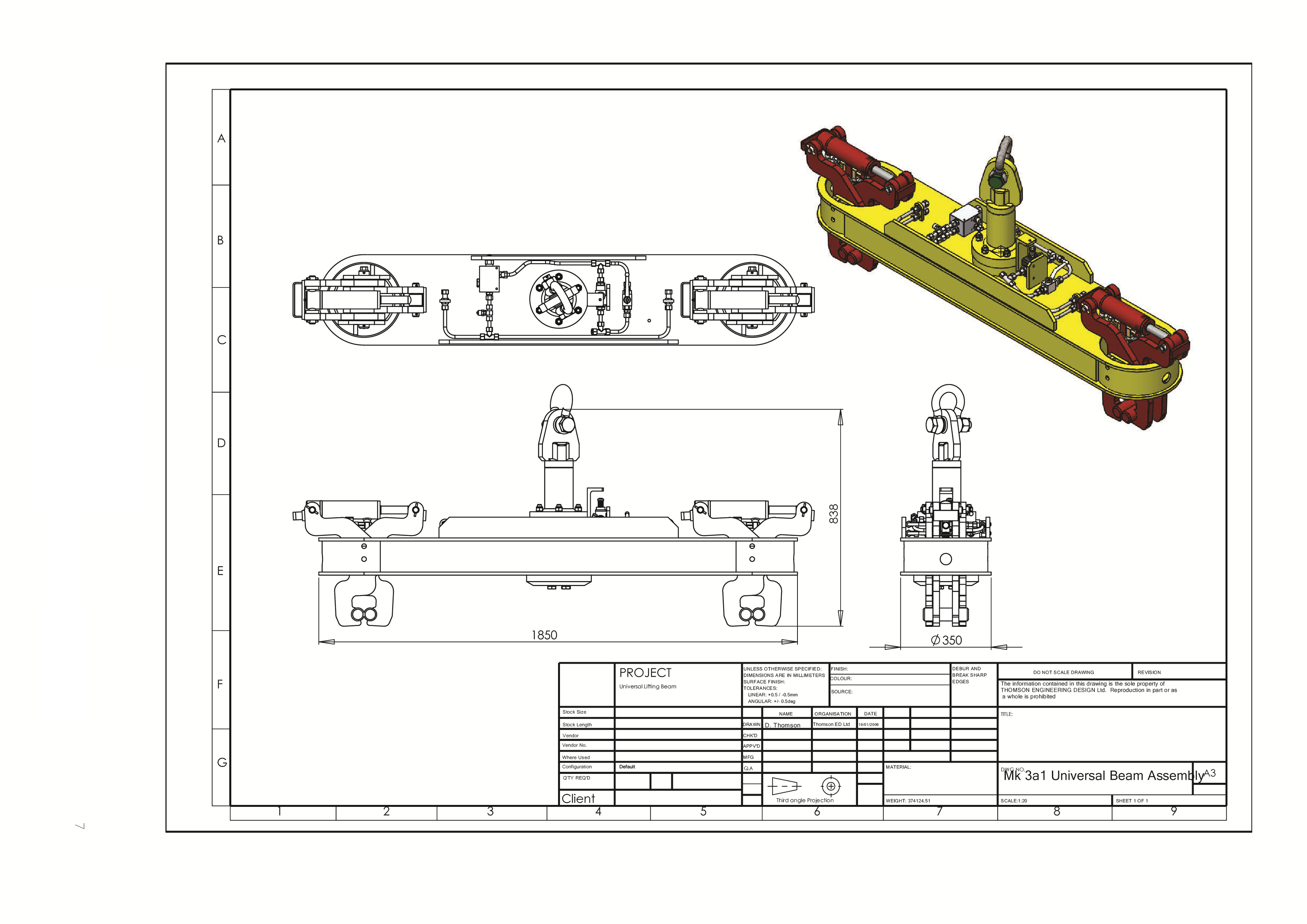
Key features and specifi cations for the Thomson Engineering Design Universal Lifting Beam for tandem lifting of track panels and for handling rails
UB02 UNIVERSAL LIFTING BEAM Specification
Introduction
The Thomson Engineering Design UB02 Universal Lifting Beam has been the industry standard solution for tandem handling of track panels since it was fi rst introduced in 2002.
Powerful hydraulic jaws grip the rails allowing track panels to be lifted out of the ballast and loaded onto rail wagons or trucks.
Each beam has a 10,000kg working load giving plenty of strength when lifting panels from frozen or compacted ballast.
The jaw assemblies can be rotated, allowing the same beam to carry individual lengths of rail and challenging loads such as points frog sections.
Universal Lifting Beams can be fi tted with low headroom shackle-type adapter heads for attachment via a swivel hook, with swivel heads for attachment via a fi xed hook or with a hydraulic rotator and adapter head (not recommended for tandem lifting operations.
A full suite of safety features are incorporated into the design including pilot operated check valves on the jaw cylinders, a parachute valve to lock the jaws during the lifting operation and built-in pressure control to protect the hydraulic circuit.
For handling scrap rail where it is often desirable to drop rails into a scrap container, the parachute valve system can be bypassed by releasing a padlock and turning a hand lever. The use of a padlock on this mechanism ensures that supervisors have full control over the agreed safe system of work.
Universal Lifting Beams are available in 1000mm / 1065mm, 1435mm (standard) gauge and 1600mm gauge versions.
All beams are proof load tested to 15,000kg and certifi cated prior to despatch from the factory and the design has been subjected to exhaustive testing and computer analysis.
All Thomson products are designed and manufactured under our ISO9001:2015 approved quality assurance processes and are built to be safe and reliable throughout a long working life.
Key Features
The tall jaw design grips the rails below the rail heads and does not require any ballast to be removed.
With a ten tonne working load limit, Universal Lifting Beams have plenty of strength for pulling track panels from bound or frozen ballast.

The ability to release the jaws from the cab of the host machine eliminates the risks of working at height associated with the use of lifting chains and straps.

For single working a rotator and adapter head can be factory fi tted to suit any host machine.

Revolve the jaw assemblies in the ends of the beam and it becomes a rail handling beam, improving utilisation.

The jaw cylinders are fi tted with pilot operated check valves which automatically lock them in the event of a burst hose or host machine failure.
The narrow gauge Universal Lifting Beam shown here can be adjusted to suit both 1000mm and 1065mm gauge track panels.

A precision pressure reducing valve limits the pressure applied to the grab cylinders to 90 Bar.
Because of this valve, Universal Lifting Beams can be used with machines producing any pressure between 90 Bar and 325 Bar.

When tandem lifting with gantry cranes, particularly with tracked gantry cranes it can be diffi cult to synchronise the speeds of the cranes. This can lead to the cranes pulling against each other, potentially causing an overturn event.
Fitting the special roller jawed Univeral Lifting Beam to one of the gantries removes this risk.

Specifications
Tare Weight (typical spec.) 225 kg
Working Load Limit 10,000 kg
Proof Load (factory test) 15,000 kg
Application Panel Handling, Rail Handling
Transport Dimensions – swivel head version
– std gauge(L x W x H) 1704 x 350 x 400 mm
Maximum Hydraulic Pressure 325 Bar
Minimum Hydraulic Pressure 90 Bar
Pressure Control Pressure Reducing Valves
System Pressure 90 Bar
Jaw Grip Force 25.4 kN


Contact Details
All technical and sales enquiries should be directed to Thomson Engineering Design.
Thomson Engineering Design Ltd Units 2a & 3 Crabtree Road Cinderford Gloucestershire UK GL14 2YN
Tel: +44 (0) 1594 82 66 11
Email: sales@thomsondesignuk.com , technical@thomsondesignuk.com
PLEASE NOTE
Whilst every care is taken to ensure that the contents of this document are true and accurate, the specifications of our products and the scope of our services are constantly changing as part of our policy of continuous improvement.
We strongly recommend contacting the factory to ensure that details given are still current.
More than half our business comes from special products designed and built as one-off’s and we are always pleased to discuss amended specifi cations should the product detailed here not meet your exact requirements.

