Specifications and Options for the UK7SB19-03 Sleeper Spreader Beam
Issue 4 July 2022
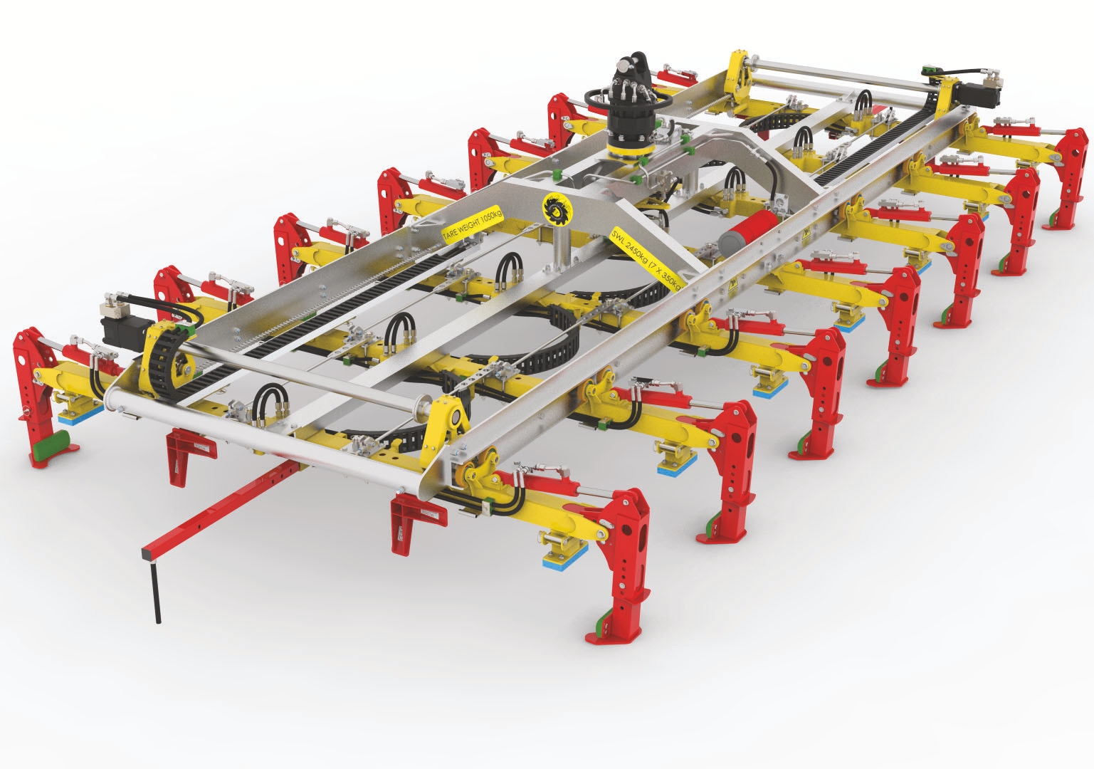
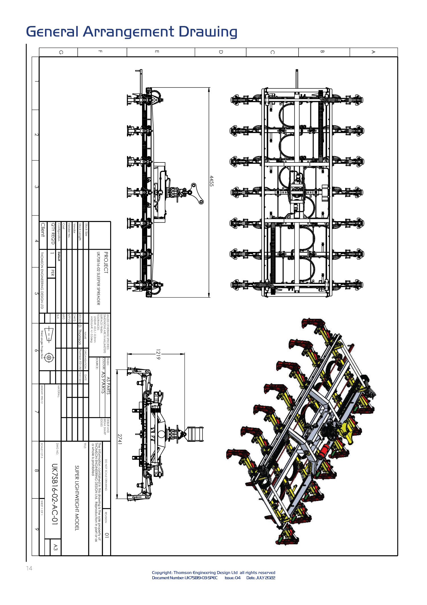
UK7SB19-03 7-Sleeper Spreader Beam Specifications
Introduction
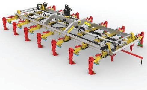
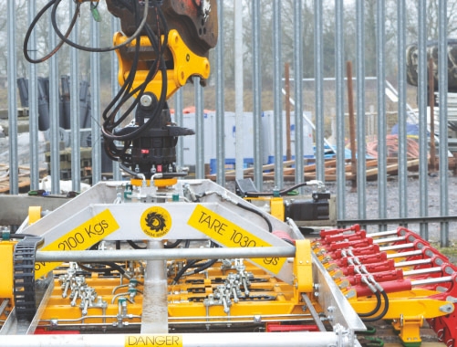
The UK7SB19-03 Sleeper Spreader is a strong and robust 7-sleeper spreader beam for handling all UK sleeper types.
The device may be used to handle sleepers and stacked-on timber dunnage, lifting the dunnage with the sleepers and eliminating the need for working at height. The UK7SB19-03 can even be equipped with its own hydraulic power pack and radio control equipment for use with gantry cranes.
The UK7SB19-03 is a modular design and is one of a range of sleeper spreader beams available from Thomson Engineering Design. Within this range are models for handling from 4 to 28 sleepers, with steel or aluminium alloy frames and for handling standard, broad and narrow gauge sleepers.
This document introduces the UK7SB19-03 Sleeper Spreader Beam which is an alloy framed unit fully approved by Network Rail for use on UK rail infrastructure projects. Two models are available, Standard and Long Chassis. The Standard Chassis allows sleepers to be set at up to 654mm centres, the Long Chassis extends this to 800mm.
Our products are constantly evolving and new features and designs are being added all the time. For the most up-to-date information please contact us.
Thomson Engineering Design Ltd
Valley Road
Cinderford
Gloucestershire
GL14 2NZ
Tel: +44 (0) 1594 82 66 11
Email: sales@thomsondesignuk.com
Specifications
Weight with typical adapter head (STANDARD) 998 kg
Weight with typical adapter head (LONG CHASSIS) 1,080 kg
Max Load Capacity (7 x 350kg sleepers) 2,450 kg
Sleeper Width Capacity:
Minimum Width: 225 mm
Maximum Width: 375 mm
Sleeper Depth Capacity:
Minimum Depth: 160 mm
Maximum Depth: 350 mm
Rotator type Vane Drive
Rotator Hyd. Pressure (max). 210 Bar
Rotator Capacity 10,000 kg
Grab / Spread Hydraulic Pressure
Minimum: 90 Bar
Maximum: 210 Bar
System Pressure Limit* 150 Bar
* A pressure reducing valve is fi tted as standard to limit the system pressure to 150 Bar irrespective of supply pressure.
Grip force:
Per Leg lateral (@150 Bar) 7.5 kN
Spread / Gather force (@150 bar) 20.3 kN
The UK7SB19-03 model is available with the full range of adapter heads.
The support legs may be set to land in the rail seats or on the sleeper ends.
Delicate & Precise Sleeper Handling
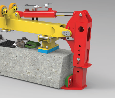
Sleepers are at risk of damage from the contact feet if the spreader beam is dropped violently onto the stack and from the grab legs when the legs close under hydraulic force. To eliminate the risk of damage these contact points on our spreader beams are fitted with large, plastic pads.
The pads on the grab legs are soft and have a high coeffi cient of friction which increases the security of the grip. The pads on the landing legs are of a harder grade with a lower coeffi cient of friction to allow the sleepers to slide into position more easily when gathering loose sleepers together.
To pull a loose layer of sleepers tightly together for more precise positioning the cross beams at each end of the UK7SB19-03 are fitted with gathering hooks. These steel hooks have a large contact area to minimise the chance of marking the sleeper face.
The grab legs are adjustable for length to allow the device to cope with different sleeper types.
The contact foot assemblies are tall enough to accommodate timber dunnage on the top of the sleepers and may be set to land either in the rail seats or on the sleeper ends.
Gathering hooks on end cross
beams
Contact feet may be set to land in the rail seats or on the sleeper ends
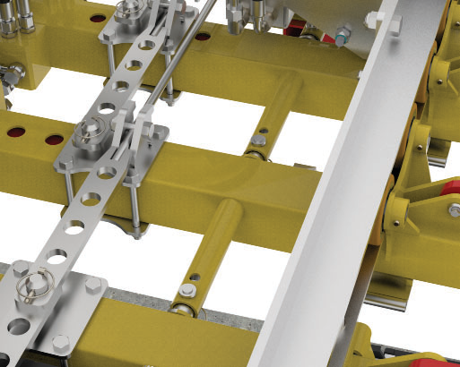
Each grab leg has its own hydraulic cylinder but tie rods running inside the main cross beam tube ensure that the legs close evenly to precisely align the rail seats on all seven sleepers.
Each hydraulic cylinder is fi tted with a twin pilot-operated check valve to lock the sleepers in the event of a hydraulic system failure or burst hose.
Both end cross beams are also fi tted with a positioning arm. These arms have a short length of hydraulic hose which is aligned with the middle of the last sleeper to be laid to set the sleepers at the correct spacing from those already laid.
The positioning arms are set to the correct spacing using a spring peg system.
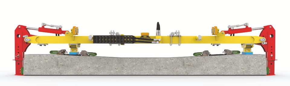
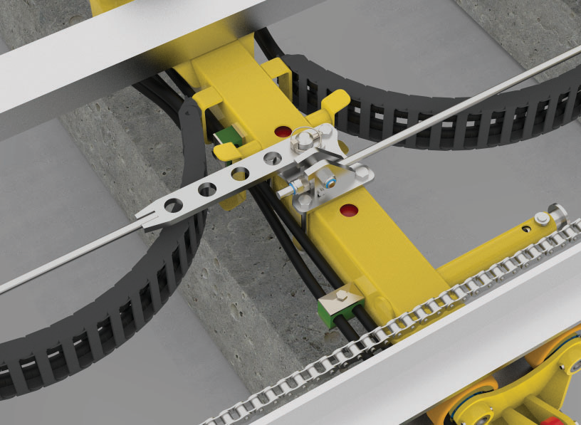
Precision Synchronised Spreading
Most designs of sleeper spreader beam employ hydraulic cylinders to spread the sleepers to the correct spacing. Generally a pair of cylinders is used, pushing in opposite directions, to drive the grabs outwards from the centre of the beam.
The diffi culty with that system is synchronising the movement of the two cylinders – any difference in the friction of movement of the grabs at one end compared to those at the other results in one end spreading fi rst and the beam becoming imbalanced. In extreme cases the beam can tip so far that sleepers slide out of the grabs and drop to the ground.
This requires complex and expensive valve systems. Even with these expensive components fitted however, changes in the hydraulic fl ow from the host machine and changes in the temperature of the hydraulic fl uid can still imbalance the system.
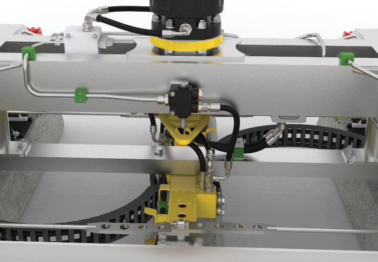
Our unique synchronised spreading system works in a completely different way to avoid any chance of imbalance. Instead of hydraulic cylinders, the sleepers are spread by powerful hydraulic motors and twin chain drives to spread the sleepers evenly, accurately and in perfect balance every time.
The motors are connected in series so that they are forced to rotate at identical speeds ensuring that the two ends of the sleeper spreader are perfectly synchronised.
Tie rods between each of the sleeper grab assemblies set the correct sleeper spacing. On the standard model these are preset to give either 28, 30 or 32 sleepers per 60ft of rail. On the Long Chassis model sleeper spacing up to 800mm may be set.
Tie rod sets are available to suit each customer’s requirements. They are precision made and have a micrometer adjustment to account for wear.
The device is preset at the factory for the standard UK sleeper width of 285mm however sleepers from 225mm to 375mm may be handled by adjusting the closure stops on the cross beams.


Simple Set-up, Simple Operation
No tools are required to adjust the UK7SB19-03 Sleeper Spreader Beam for different sleeper types and different sleeper spacings.
The tie rods between the sleeper grab assemblies are accurately set at the factory to give the agreed sleeper spacings simply by fi tting the correct hole on each tie rod over the pegs on the cross beams. Sleeper spacing can be altered in a few minutes.
Most UK sleepers are 285mm wide but, should you need to work with a different sleeper type simply unpin and adjust the closure stops.
Similarly the length of each leg can be quickly adjusted to suit different sleeper types by removing the cross pins.
The landing legs can be positioned in the rail seats or at the sleeper ends using the pinned attachment points provided on the bottom face of the cross beams. The height of the landing legs allows for timber dunnage placed on the top of the sleepers to be lifted with the sleepers – eliminating the need for personnel on the sleeper stacks.
Once the UK7SB19-03 is correctly set its operation is very simple.
Automatic changeover valves detect when the sleeper spreader is lifted and transfer control from the grab legs to the spreader system so the operator only has to think about one control: put the device down and the grab legs operate, pick it up and the spreader system operates (see note).
This also makes it impossible for a fatigued operator to inadvertently release the sleepers in mid air.
NOTE
If required the device can be supplied with independent control of sleeper grip and spacing funcƟ ons.
This requires a third hydraulic service from the host machine.
Adjust the closure stops for different sleeper widths
A simple pin system sets the leg length for different sleeper types
Set different sleeper spacings by selecting the correct hole in the tie rods to fit on the cross beam pegs. Standard tie rods provide 610mm, 653mm and 703mm spacing. Other rods are available to order for different spacings up to 800mm (on Long Chassis model)
Load sensing valves automatically detect when the UK7SB19-03 is lifted and close off the operator’s control of the grab legs – transferring control to the spreader mechanism on twohydraulic-service models
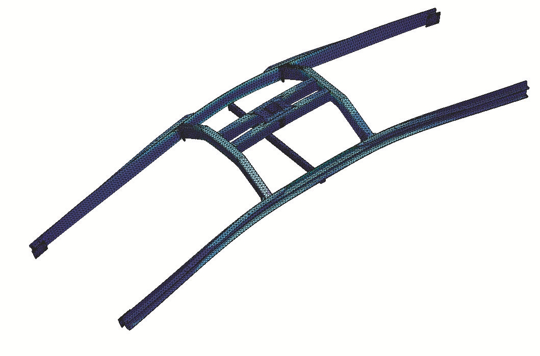
Heavy Duty Construction
The UK7SB19-03 Sleeper Spreader Beam is designed for a long, hard working life. All parts of the design have been subjected to rigorous computer analysis to ensure that nothing is over stressed in normal use.
Sleeper spreader beams work in a diffi cult environment and operators are always under pressure to
work as quickly as possible. The inevitable result of this is the occasional accidental bump.
If the beam gets damaged, all parts of the device are replaceable and the beam is simple to dismantle
and re-build so repairs will not tie up skilled staff for long.
A great deal of time has been spent during the design phase in reducing the cost of the most vulnerable
parts such as the grab legs so that accidental damage doesn’t cost too much either.
Adapter Head Options
Each UK7SB19-03 Sleeper Spreader is factory equipped with an adapter head to suit your host machine.
Adapter heads are available for all popular fitments from a simple yoke attachment for direct fitment to the boom to interchangeable head systems for multiple attachments.
Here we show just a few of the options available
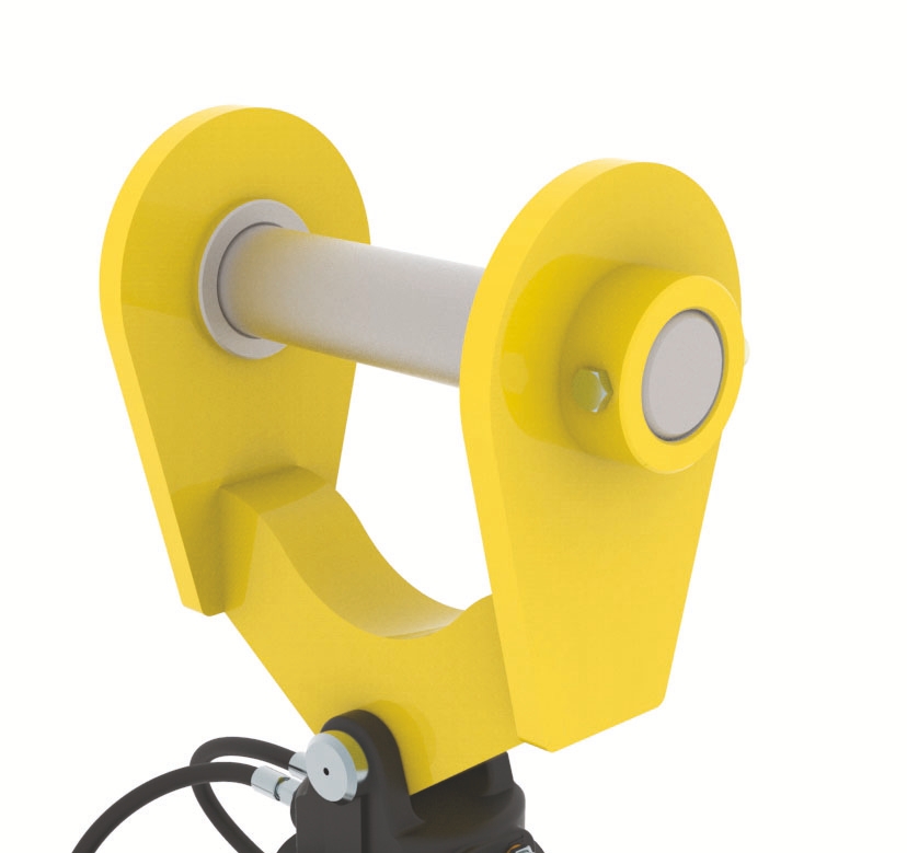
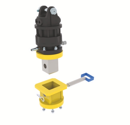
A simple yoke adapter with removable pin for fitting directly to the boom-end boss of the host machine
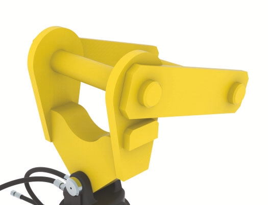
A two-pin adapter head for use with a standard quick coupler
Some modern quick couplers must be crowded right in before they can be released from the attachment. This special two-pin adapter head allows this to be done without tipping the attachment.
A two-pin adapter head for use with a standard quick coupler
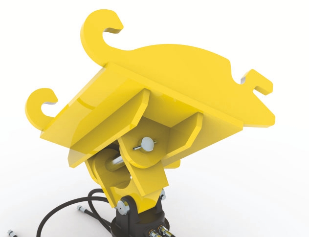
A two-pin adapter head for use with a standard quick coupler
All technical and sales enquiries should be directed to Thomson Engineering Design.
Thomson Engineering Design Ltd , Units 2a & 3 Crabtree Road , Cinderford , Gloucestershire , UK , GL14 2YN
Tel: +44 (0) 1594 82 66 11
Email: sales@thomsondesignuk.com
PLEASE NOTE
Whilst every care is taken to ensure that the contents of this document are true and accurate, the
specifi cations of our products and the scope of our services are constantly changing as part of our
policy of continuous improvement.
We strongly recommend contacting the factory to ensure that details given are still current.
More than half our business comes from special products designed and built as one-off’s and we are
always pleased to discuss amended specifi cations should the product detailed here not meet your
exact requirements.